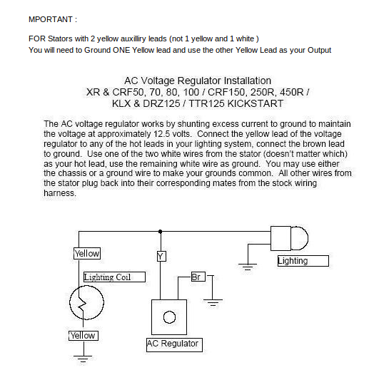
Trail Tech Voltage Regulator Wiring Diagram. Puch uses separate coils/ wires for taillight, Headlight and brakelight. I did check the alternator (dynamo in Kubotese) output which appears to After thinking about this a little more: I'm guessing that I'm supposed to "transfer" the wire colors on the connector to the regulator ignoring the actual wire colors.
Like the diagram shows, I left the black mounting block on the back of Oh make certain to mount the voltage regulator so that the case is grounded really well.
The magnitude of the voltage produced by these generators depends upon the RPM of the engine.

Trail Tech Voltage Regulator Wiring Diagram - Wiring Diagram
z50 K2 and Lifan 125 Wiring

YFZ450 Custom Wiring Harness - Yamaha YFZ450 Forum ...
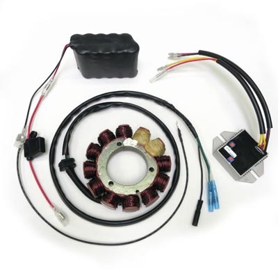
Ricky Stator - Products

Polaris Charging problem | Doovi

z50 K2 and Lifan 125 Wiring
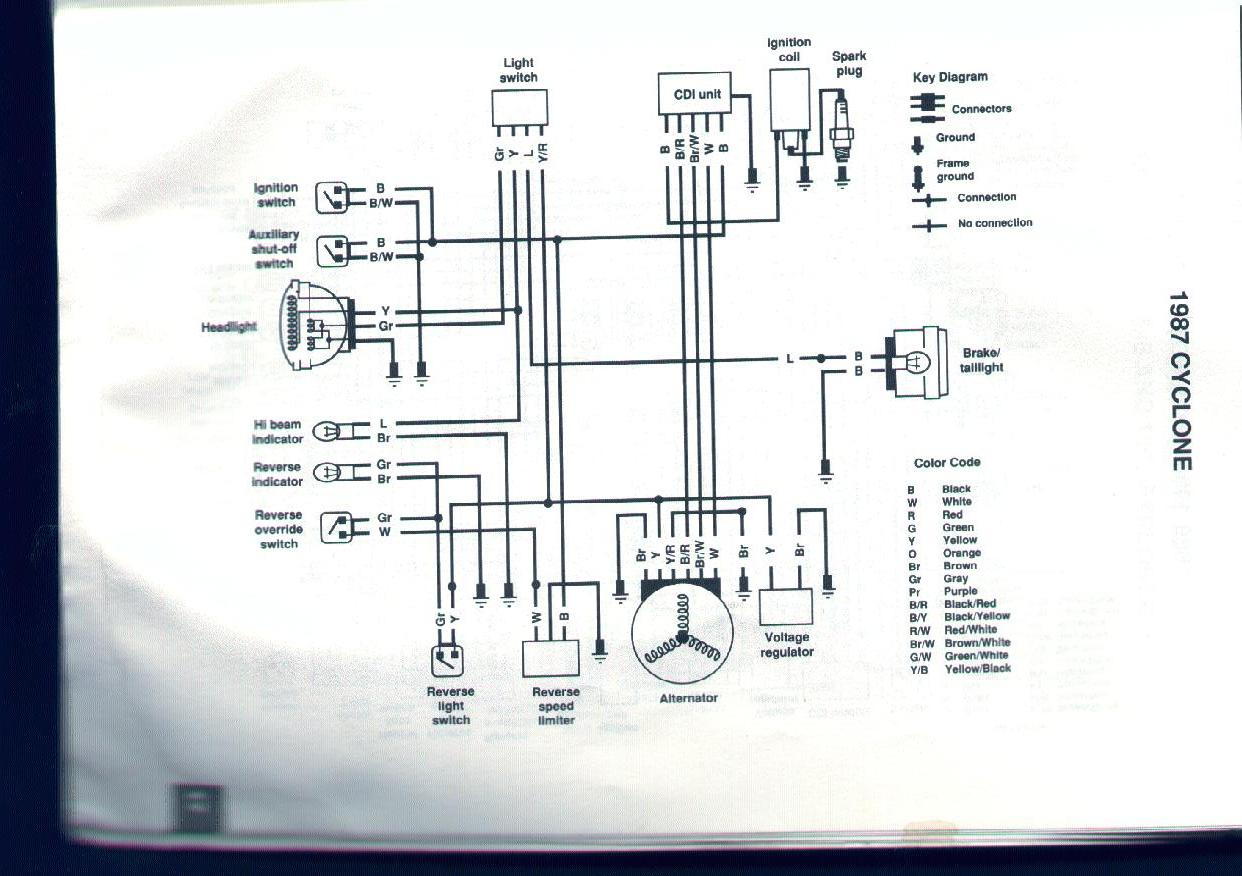
cyclone 250x what do I need (electrical components ...

Stator Trail Boss 325 Polaris

Tecumseh Minibike AC Wiring - Home of the Pardue Brothers
Stator must have a floated ground Wire connection for use with most machines. Linear voltage regulators, also (somewhat inaccurately) called LDOs, are one of the most common electronic components. Definition: The induction voltage regulator is a type of an electrical machine in which the output voltage may be varied from zero to a certain maximum value depending upon the ratio of turns in The schematic diagram of the single phase induction voltage regulator is shown in the figure below.